


Introduction
A second-order analysis estimates the amplification of bending moments caused by the compression force acting on the deformed shape of the column. The initial eccentricity triggers a lateral deflection, which in turn increases the bending moment, which increases the deflection further. The Eurocode's nominal curvature method quantifies this effect through a second-order eccentricity derived from the section curvature and the effective buckling length , without requiring a full nonlinear FEM model:
SectionPro evaluates the curvature from a nonlinear analysis at each load level, then applies the Eurocode formula above to obtain . The axial force is increased, tracing a load path on the interaction diagram until either the material capacity is reached (resistance) or the eccentricity diverges (buckling instability). Two modes are available:
- 2D uniaxial: buckling is analysed in one bending plane (– or –). The other moment component is held constant, and an optional first-order moment can be imposed.
- 3D biaxial: both bending planes are amplified simultaneously, each with its own buckling length and . The load path is traced on the full 3D interaction surface.
Computed results
SectionPro reports for each buckling analysis:
Load path
Capacity reduction
Exports
Solid circular column (slender)
Input data
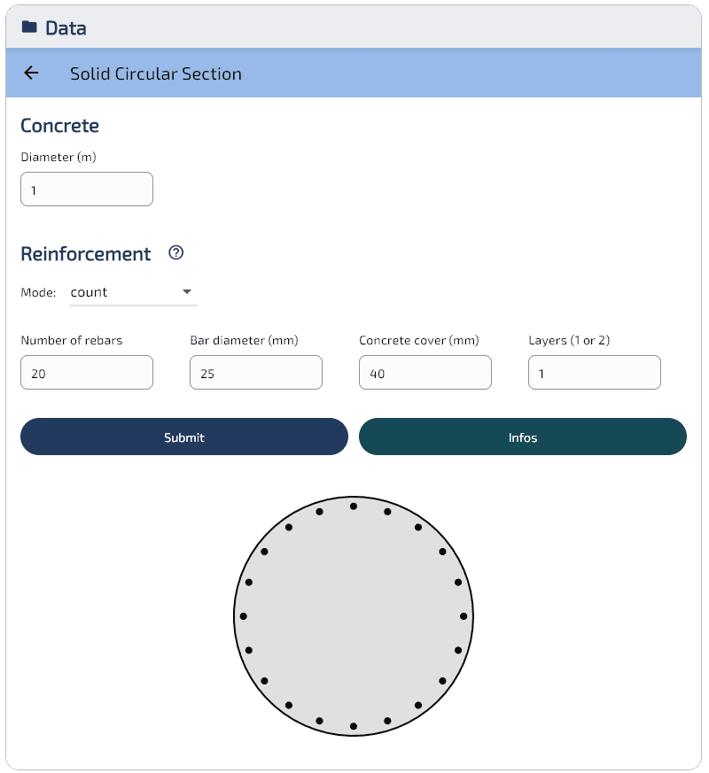
- Concrete — Solid circular cross-section, diameter m, area m².
- Reinforcement — 20 bars HA25 ( mm), positioned at mm, cover 40 mm, 1 layer, cm².
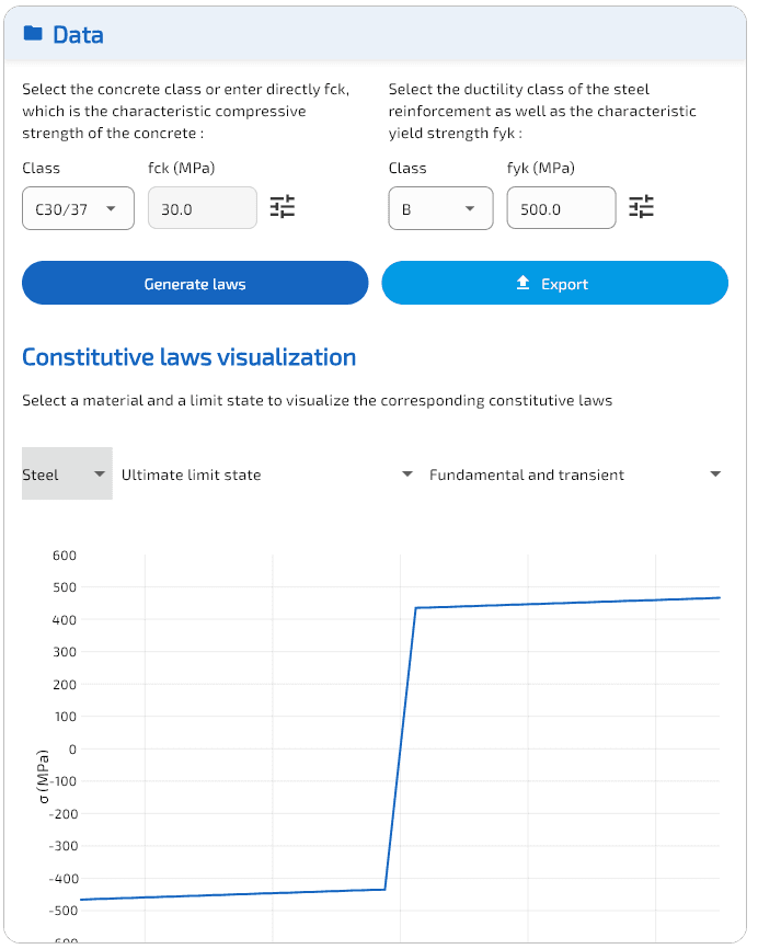
- Material laws (EC2) — Concrete C30/37: MPa, Steel B500B: MPa.
2D uniaxial buckling (N–Mz plane)
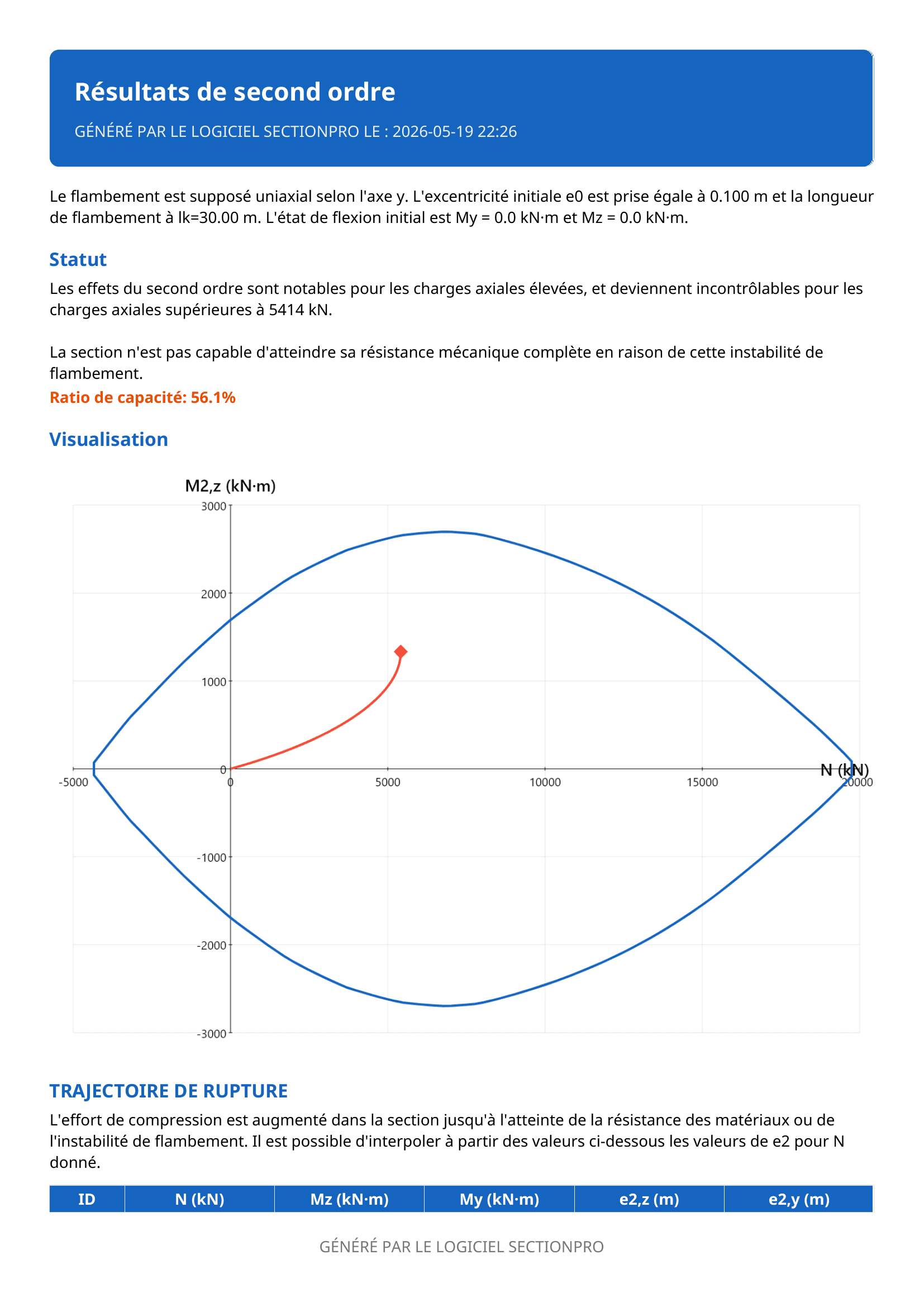
The column has an effective buckling length of m with an initial eccentricity m and no first-order moment ().
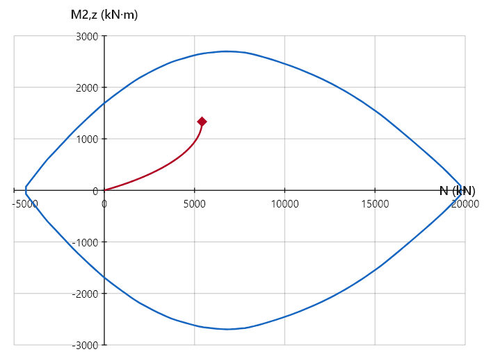
With a slenderness ratio , this column is highly slender. The load path is nearly linear up to about kN, where second-order effects remain small. Beyond this point, the eccentricity grows rapidly and the load path curves sharply upward. The column fails by geometric instability at:
- kN
- Capacity reduction: 53%
- At 25% of the maximum compressive resistance ( kN out of kN): total moment kN·m, of which kN·m is second-order (46%)
For this slender column, second-order effects are already severe at a fraction of the axial capacity.
Hollow circular column
Input data
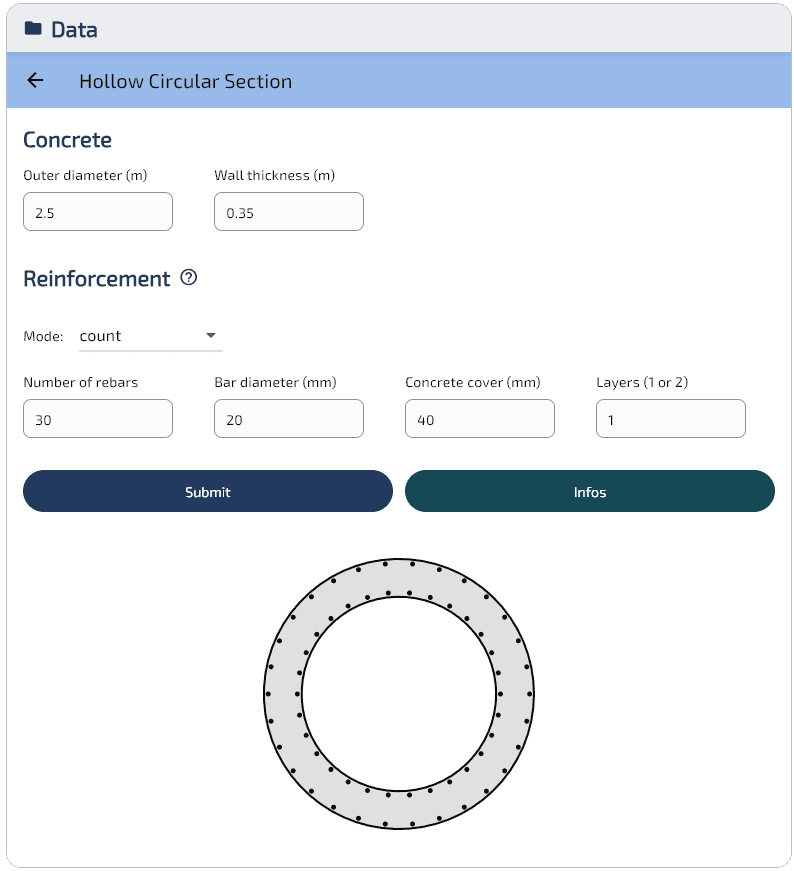
- Concrete — Hollow circular cross-section, outer diameter m, wall thickness m, inner diameter m.
- Reinforcement — 30 bars HA20 ( mm), positioned at mm (outer layer), cover 40 mm, 1 layer, cm².
- Material laws (EC2) — Concrete C30/37: MPa, Steel B500B: MPa.
2D uniaxial buckling (N–Mz plane)
The column has an effective buckling length of m with an initial eccentricity m and no first-order moment ().
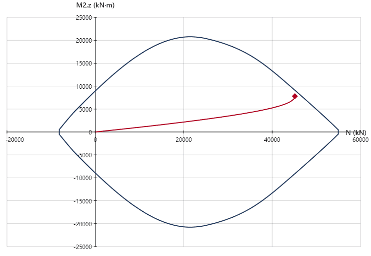
With a slenderness ratio , this column is stocky. The load path is nearly linear for most of the range, but the eccentricity starts to accelerate noticeably beyond kN. Unlike the slender column where this acceleration occurs early, here it only appears when is already close to the maximum compressive resistance. The column fails just before reaching the interaction curve:
- kN
- Capacity reduction: 1.3%
- At 25% of the maximum compressive resistance ( kN out of kN): total moment kN·m, of which kN·m is second-order (17%)
Second-order effects only become noticeable as approaches the maximum compressive resistance.
3D biaxial buckling
In 3D mode, SectionPro amplifies the bending moments in both planes simultaneously. Each direction has its own buckling length (, ) and initial eccentricity (, ), and the second-order eccentricities and are computed independently at each load level.
The hollow circular column is analysed with symmetric buckling lengths: m with m. No first-order moments are applied.
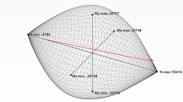
With a short buckling length of 10 m, second-order effects are negligible throughout the load path. The eccentricity remains below 1 mm for most of the range and only reaches mm at the very last point. The load path is essentially linear and reaches the interaction surface at:
- kN
- At 25% of the maximum compressive resistance ( kN out of kN): total moment kN·m per axis, of which kN·m is second-order (0.5%)
The column reaches its full material resistance with virtually no capacity reduction from geometric effects, mainly due to the reduced buckling lengths and smaller initial eccentricities compared to the 2D examples.
Performance benchmark
The second-order analysis consists of two phases: building the interaction curve (or surface), then tracing the load path by incrementally computing at each load level. Each step evaluates the section curvature through an iterative algorithm. The table below shows the total computation time for 500 load path points.
| Solid circular (2D) | Hollow circular (2D) | Hollow circular (3D) |
|---|---|---|
| ms | ms | ms |
The dominant cost is building the interaction surface. The load path tracing itself adds only a few milliseconds, keeping the total analysis well under 300 ms in all cases.
Export
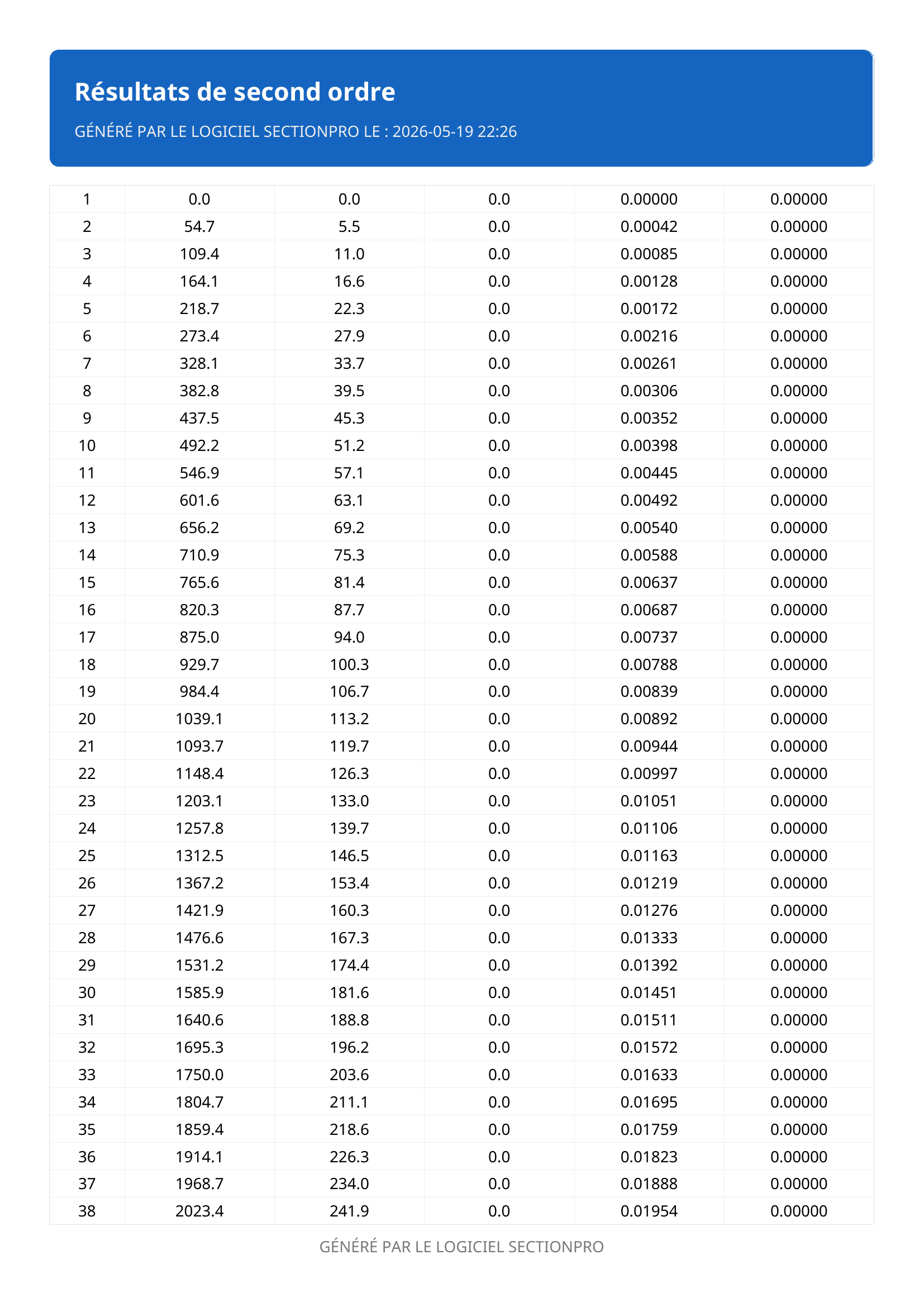
SectionPro exports the buckling analysis in three formats: PDF, text, and Excel (.xlsx). The exported data includes the full load path (, , , , at each load level), the capacity reduction factor, and the buckling status.
Conclusion
The nominal curvature method allows engineers to evaluate second-order effects at the section level without the cost and complexity of a full nonlinear FEM model. The load path visualisation on the interaction curve (or surface) provides an immediate assessment of how significant second-order effects are for a given column.
The comparison between the solid Ø1m column and the hollow Ø2.5m column demonstrates that geometric properties, not just the buckling length, govern the outcome. The slender solid column exhibits a strongly curved load path and fails by instability, while the hollow column reaches its material capacity with small second-order amplification.
The 3D biaxial mode extends this analysis to columns with different buckling lengths in each direction, amplifying moments independently in both planes.