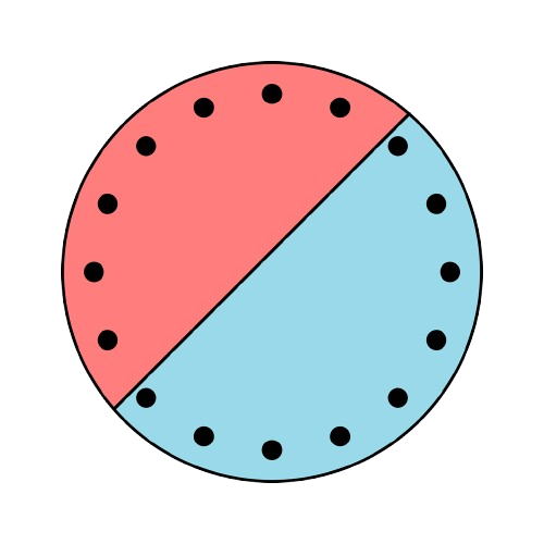


Introduction
The fire calculation is performed in two successive steps. The first step is thermal, as described in the previous article: SectionPro solves the heat transfer problem on the real cross-section and returns the temperature field in the concrete, the reinforcement and any embedded steel profile at each requested instant.
The second step is mechanical. For each selected fire duration, the mechanical modules start from the corresponding temperature field and derive the resisting section used for verification. The concrete contribution is reduced according to the heated region of the section, while the reinforcing bars and embedded steel profile receive temperature-dependent mechanical properties. The resulting heated section is then analysed in the same spirit as an ambient-temperature section: load-case verification, interaction curves and surface, distances, stiffness curves and time to failure.
The 500 °C isotherm method
For the concrete, SectionPro follows the 500 °C isotherm method of EN 1992-1-2. Concrete heated above 500 °C is discarded; concrete that has stayed below 500 °C is retained with its full strength at ambient temperature and its usual parabola-rectangle law (‰, ‰). The resisting geometry therefore reduces to the region enclosed by the 500 °C isotherm, which contracts as the exposure grows.
Each reinforcing bar is reduced at its own temperature: its yield strength and modulus become and , with the reduction factors of EN 1992-1-2 (Tables 3.2a and 3.2b). A bar lying outside the 500 °C isotherm is not removed; it still contributes at its reduced strength.
The same treatment applies to an embedded structural profile when it is meshed in the thermal step: each steel element is read at its temperature, reduced by and , and the concrete it occupies is removed so that it is not counted twice. Once the heated section has been built, the mechanical verification proceeds like a standard section analysis, with fire affecting the resisting geometry and the material laws used at the selected instant. On this reduced section, SectionPro runs:
- Section verification: the equilibrium of a load case, with the full stress and strain field at a given instant.
- Interaction curve: the resistance boundary in a chosen force plane, with one component fixed.
- Interaction surface: the complete 3D resistance domain in .
- Distances: the utilization of each load by projection onto that surface.
- Stiffness: the moment–curvature response and the secant and tangent flexural stiffness.
- Time to failure: the exposure time at which the load leaves the resistance domain.
The example section
The calculations are illustrated on the composite column shipped with the SectionPro examples:
- Circular section, mm, C30/37.
- Embedded HEB 600 profile in S235 steel.
- 20 Ø16 B500B bars on the perimeter.
- Standard ISO 834 fire exposure.
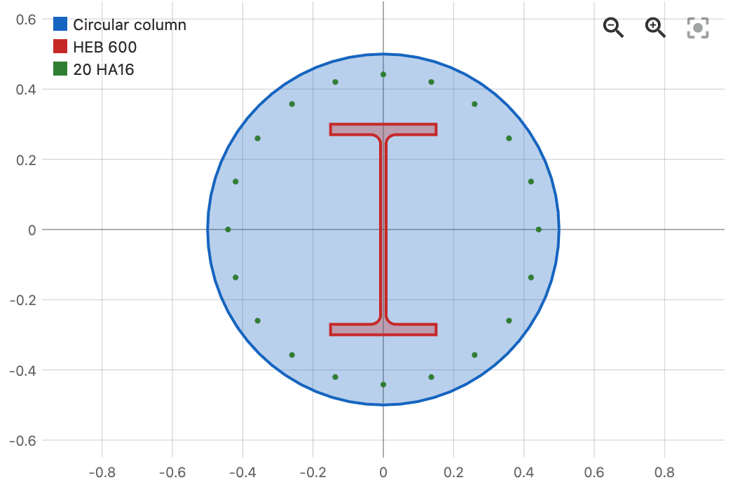
This case is deliberately richer than a plain reinforced-concrete column. The embedded profile is not directly exposed: the surrounding concrete acts as thermal protection and delays its heating. The figures that follow show how this thermal inertia translates mechanically, in both resistance and stiffness.
Section verification
For a load specified for the verification, SectionPro finds the strain state , one axial strain and two curvatures, that satisfies internal equilibrium with the imposed forces. It solves this iteratively, integrating the stresses over the heated section at each step: the retained concrete over its contours, the bars and the meshed profile as fibres, each governed by its reduced law.
From the converged strain state, SectionPro extracts the stresses and strains at every fibre, the position of the neutral axis, and a utilization defined as the ratio of the governing fibre strain to that material's ultimate strain. A utilization below 1 means the load is carried; a value of 1 or above means the reduced section can no longer balance it.
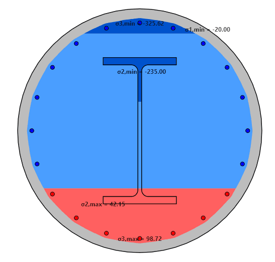
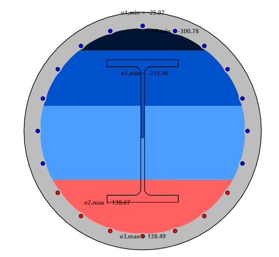
In the example the load is , in kN and kN·m. The R120 and R240 views place the same load on a section whose resisting area shrinks with exposure: the concrete inside the 500 °C isotherm carries the compression, while the bars and the embedded profile, still cool, balance the bending. At R240, the section reaches failure by crushing of the retained concrete.
N–Mz interaction curve
The – interaction curve is the resistance boundary of the section in uniaxial bending: the set of axial force and bending moment pairs it can carry about the axis under study. Recomputed for each fire duration on the reduced section, the overlaid curves give a direct view of the capacity lost to heating.
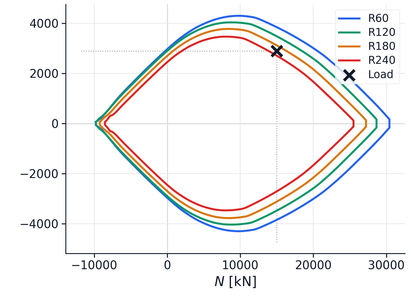
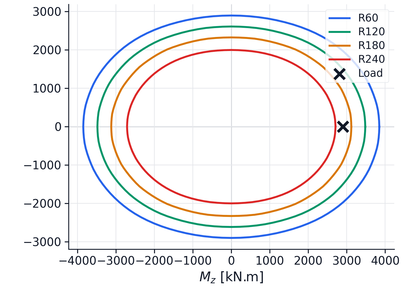
The figures show the capacity loss as the temperature increases: the resistance domains progressively contract with the fire duration. For the selected load, failure occurs between R180 and R240.
3D interaction surface
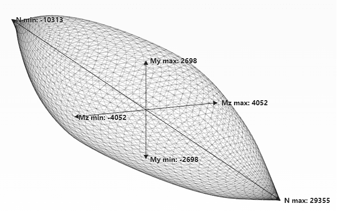
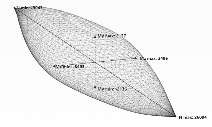
Under biaxial bending the resistance can no longer be captured by a single plane curve: it becomes a closed surface in the space, the resistance domain of the section. SectionPro computes this surface directly from the ultimate strain states of the section, taken across every direction of bending. Built on the heated section, it lets any biaxial load be checked directly, without reducing it to a preferred axis: a load inside the surface is carried, a load outside exceeds the capacity.
Distances
The distances module checks several biaxial bending load cases graphically against the same interaction surface. Each load is projected onto the surface and returned with a utilization , so the engineer can read at once which loads remain inside the resistance domain and which ones exceed it.
- : the load stays internal and the section has reserve capacity.
- : the load sits on the boundary, at the exact limit.
- : the load turns external and the capacity is exceeded.
Under fire the domain contracts with exposure, so the status of the same load can change from inside to outside as the duration increases.
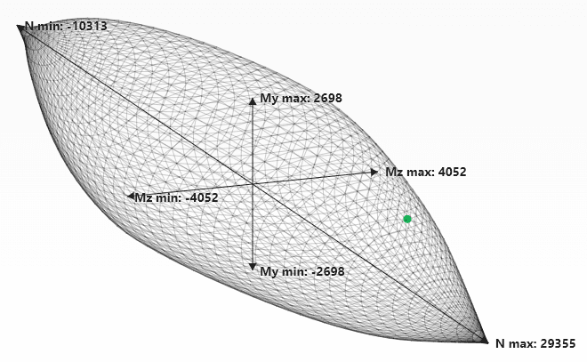
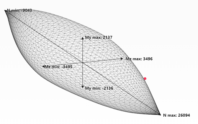
The load point moves from internal at R120 to external at R240, which is consistent with the section verification and interaction-curve results.
Fire stiffness
Heating also reduces the flexural stiffness of columns. As curvature increases, this stiffness loss can amplify second order effects even before the ultimate resistance is reached.
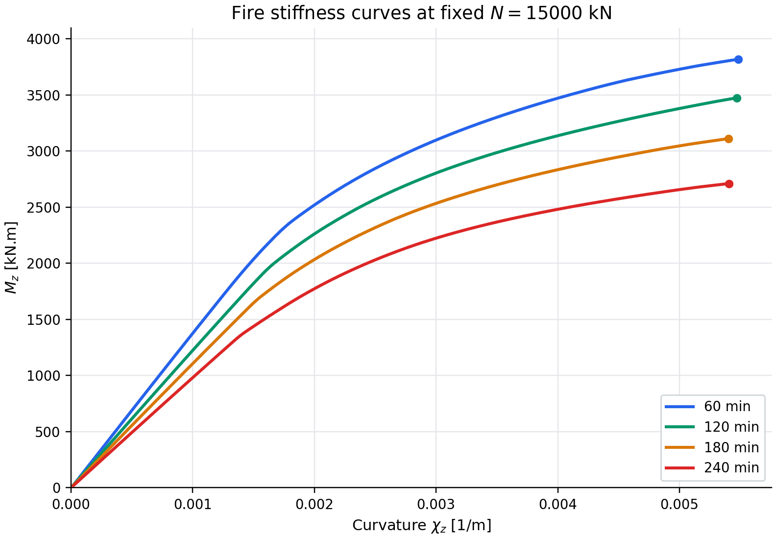
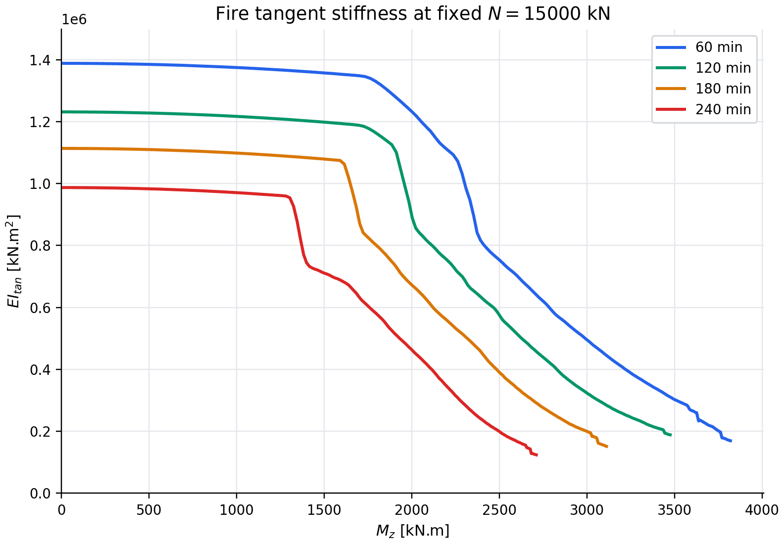
The curves show a sharp stiffness degradation with fire duration: the moment–curvature response flattens, and the tangent stiffness drops abruptly as the heated section approaches failure.
Time to failure
Time to failure is the calculation most specific to fire. For a fixed service load, SectionPro rebuilds the reduced section at each thermal output time and solves the equilibrium on it. The capacity falls as the 500 °C isotherm contracts and the steel temperatures rise; the time to failure is the instant at which the load leaves the resistance domain, when the reduced section can no longer balance it within the material strain limits.
An insulation test is then run on the same section to check whether passive protection solves this specific fire-resistance issue. The same load is evaluated first on the bare section, then with a continuous insulating layer over the concrete perimeter.
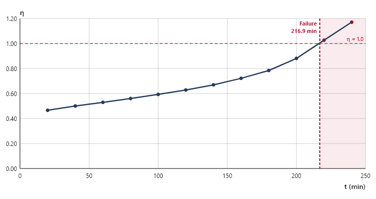
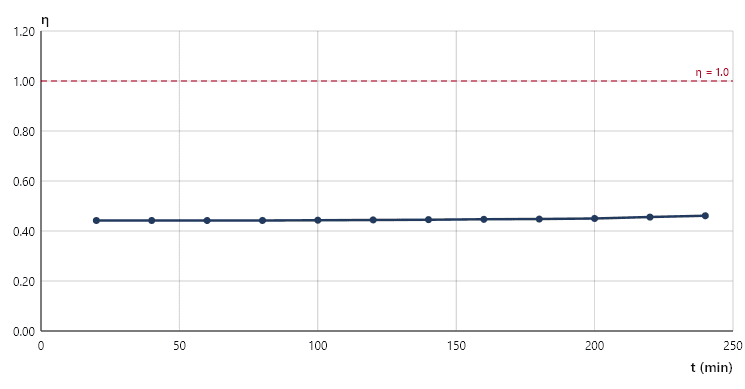
The protection is modelled as a continuous passive layer described by four thermal parameters. For this insulation test, the following values were used:
| 20 mm | 0.2 W/(m·K) | 700 kg/m³ | 1000 J/(kg·K) |
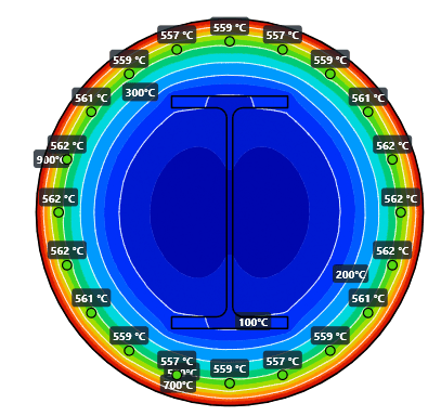
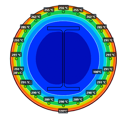
The protection is very effective in this case: the passive bars drop from about 560 °C to about 300 °C, and the concrete remains below 500 °C even after 240 min, so the whole concrete section is retained mechanically.
Software performance
The main task is the computation of the thermal field at the requested fire durations. Once these temperature fields are available, the mechanical checks are fast, and the complete workflow remains below one second for this example.
| Calculation | Time |
|---|---|
| Thermal field (2 steps, R120/R240) | 0.20 s |
| Section verification (stress-strain) | + 4 ms |
| N–Mz interaction curve (160 points) | + 31 ms |
| My–Mz domain at fixed N | + 35 ms |
| 3D interaction surface (50 × 50) | + 134 ms |
| Stiffness curve (moment-curvature) | + 11 ms |
| Time to failure (full sweep) | + 52 ms |
Conclusion
The 500 °C isotherm method turns the thermal field into a reduced resisting section: concrete kept at its strength inside the isotherm, bars and embedded steel weakened by their local temperature. From this heated state, the analysis gives the resistance of the imposed load, the interaction domains, the load distances, the stiffness loss and the time at which the load leaves the resistance domain.
On the composite column studied, the embedded profile stays shielded by the surrounding concrete and keeps a significant share of the capacity at the intermediate durations. The continuous passive protection lowers the temperatures markedly at R240 and pushes back the time to failure of the load under study.
The different calculations are consistent with each other: they all point to the same loss of capacity and to the same failure range. The section verification gives the detailed stress and strain state for one load. The interaction curve is the preferred engineering view when a resistance domain is needed in a plane. The interaction surface gives the global biaxial domain. The distance check gives a fast internal/external status for several loads. The stiffness curves show whether the section has entered a regime of strong stiffness degradation. The time-to-failure analysis finally gives an approximate exposure time before the load can no longer be carried. Each view has its own strength, and together they give a coherent reading of the fire behaviour.