

Introduction
Reinforced concrete cracks under service loads. Cracks do not compromise structural safety, but excessive openings allow water, chlorides and CO₂ to reach the reinforcement, causing corrosion. Design codes therefore limit the crack width at the serviceability limit state.
SectionPro implements the Eurocode 2 direct calculation approach. The crack width is the product of the maximum crack spacing and the mean differential strain between steel and concrete:
The crack spacing depends on cover , bar diameter , bond factor and effective reinforcement ratio :
The mean differential strain accounts for tension stiffening (concrete between cracks carries part of the tension):
The effective tension area depth is a key intermediate result computed automatically from the section geometry: .
Computed results
SectionPro provides for each crack width analysis:
Results per load case
Intermediate quantities
Exports
Rectangular slab
Input data
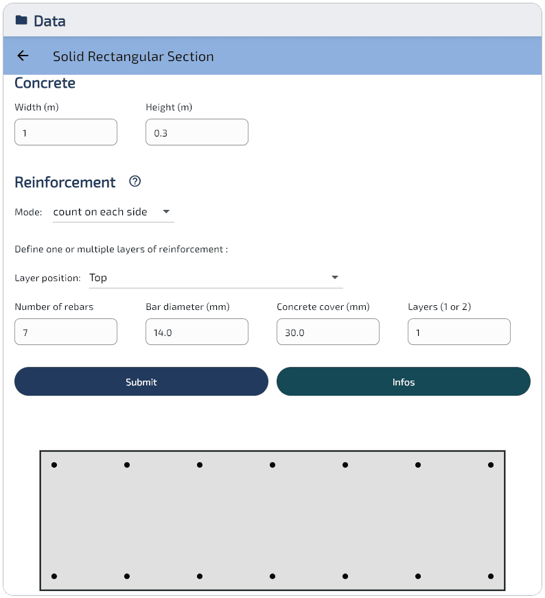
- Concrete — Rectangular cross-section, width m, depth m
- Reinforcement — 14 bars Ø14 ( mm), 7 bottom + 7 top, spacing 157 mm, cover 30 mm, 1 layer per face, cm²
- Material laws (EC2) — Concrete C30/37: MPa — Steel B500B: MPa
Results
The crack width is evaluated for two loading states: pure bending and tension-dominated. Cracking parameters are kept at their recommended values: (long-term), (high-bond bars), , , MPa.
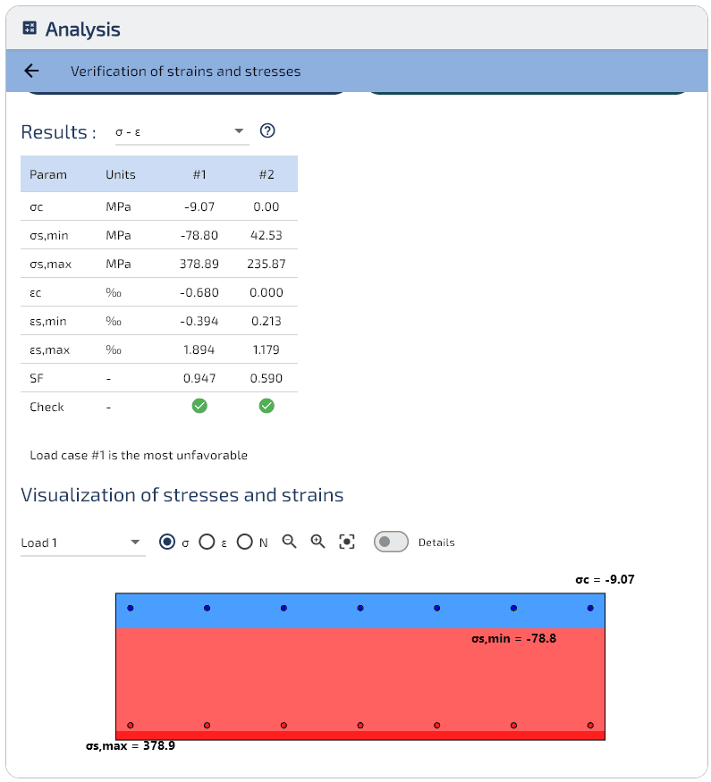
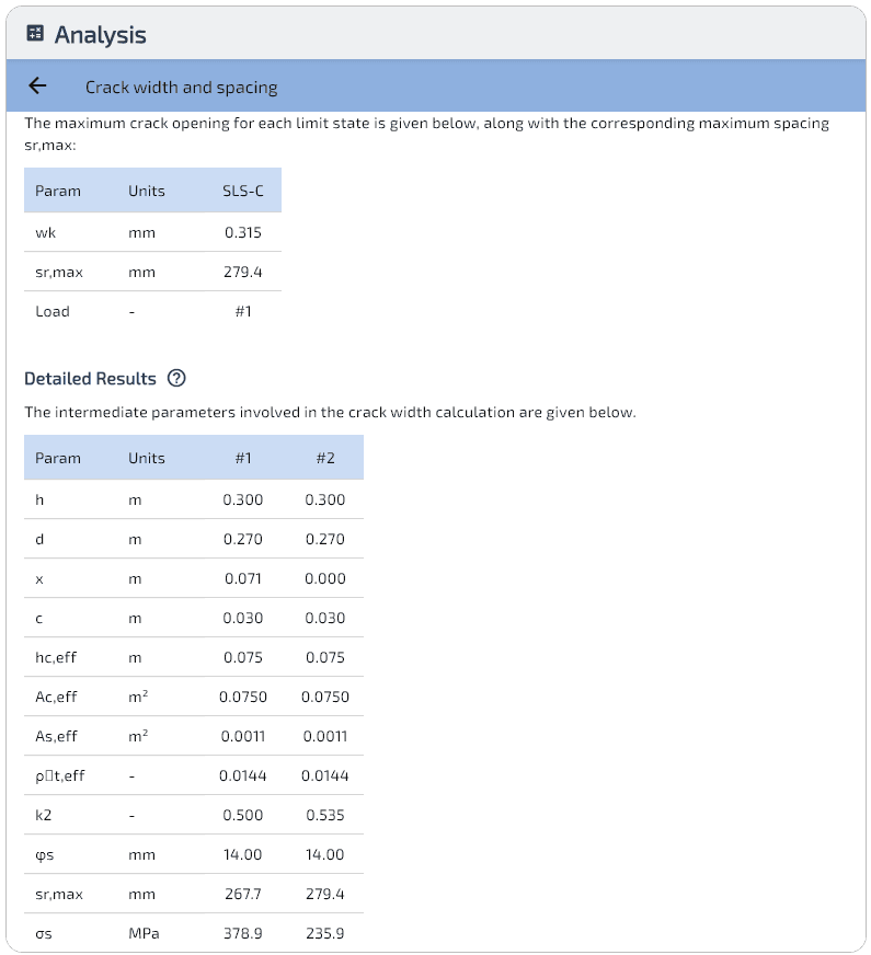
Under pure bending ( kN·m), the neutral axis lies at mm, leaving mm of the section in tension. With , the spacing formula gives mm. The crack width mm exceeds the usual 0.3 mm limit: a thicker slab or closer bar spacing would be needed in practice.
Under tension ( kN, kN·m), the entire section is cracked (). Despite full cracking, mm is smaller than in bending because all 14 bars share the load, reducing from 379 to 236 MPa. The factor reflects the slightly non-uniform strain distribution caused by the residual bending moment.
I-beam: pure bending
Input data
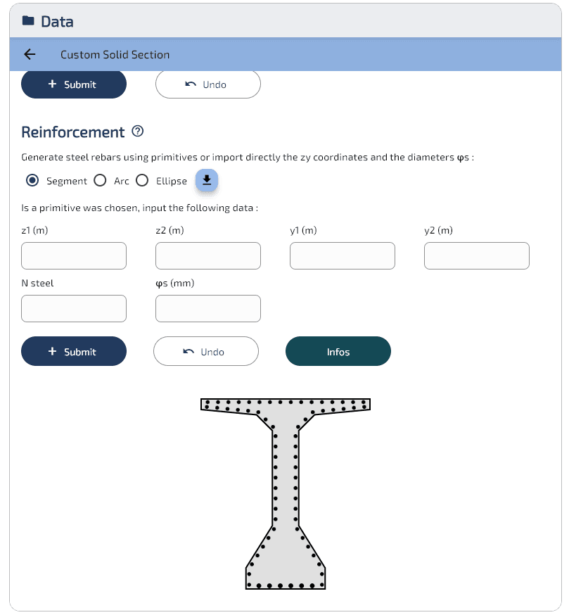
- Concrete — I-shaped cross-section with haunches, bottom flange m, web m, top flange m, total depth m
- Reinforcement (passive steel only) — 70 bars total (HA16 + HA20), 6 HA20 as bottom reinforcement, 64 HA16 distributed along the section contour
- Material laws (EC2) — Concrete C30/37: MPa — Steel B500B: MPa
Results
The I-beam is loaded in pure bending at three increasing moment levels (, and kN·m). Cracking parameters: , , , , MPa.
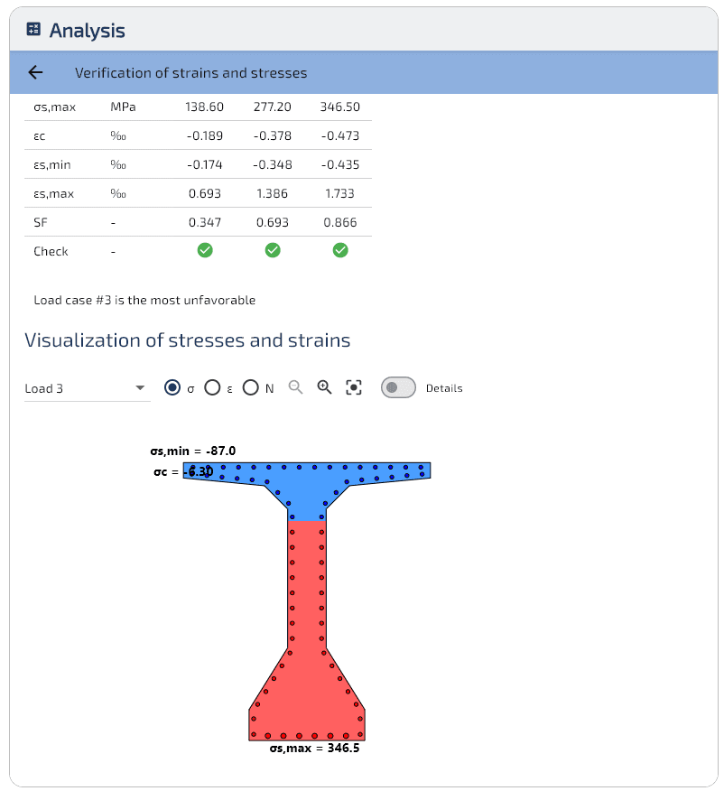
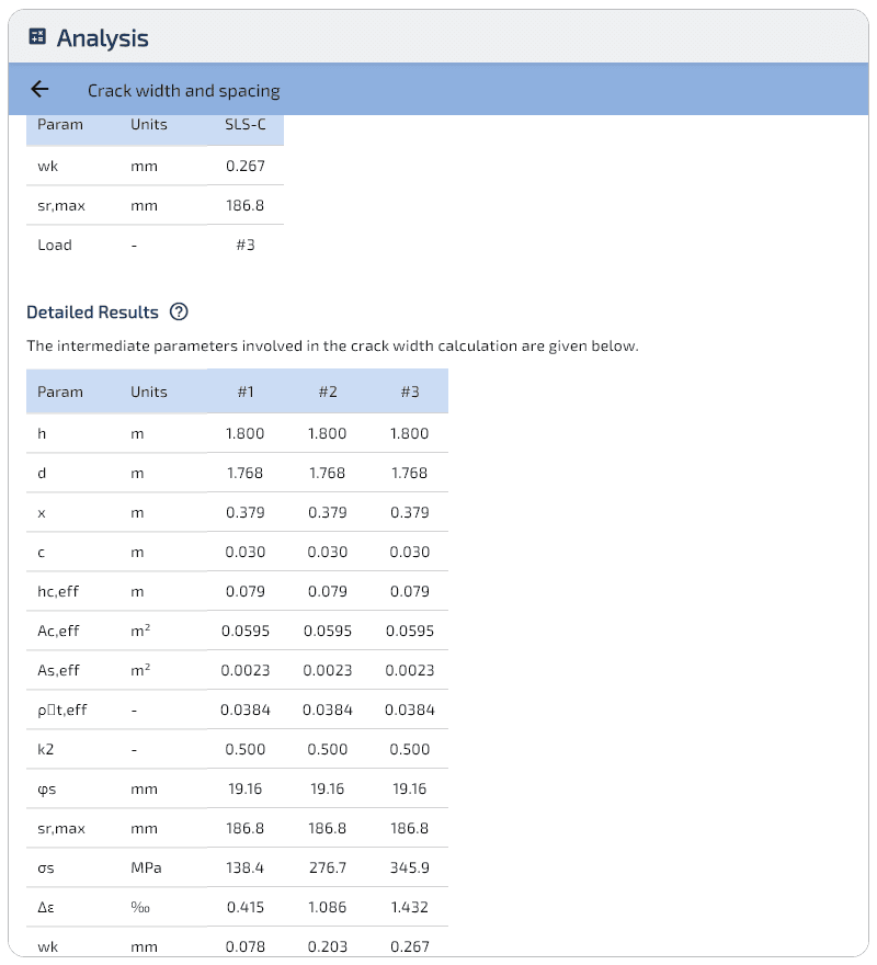
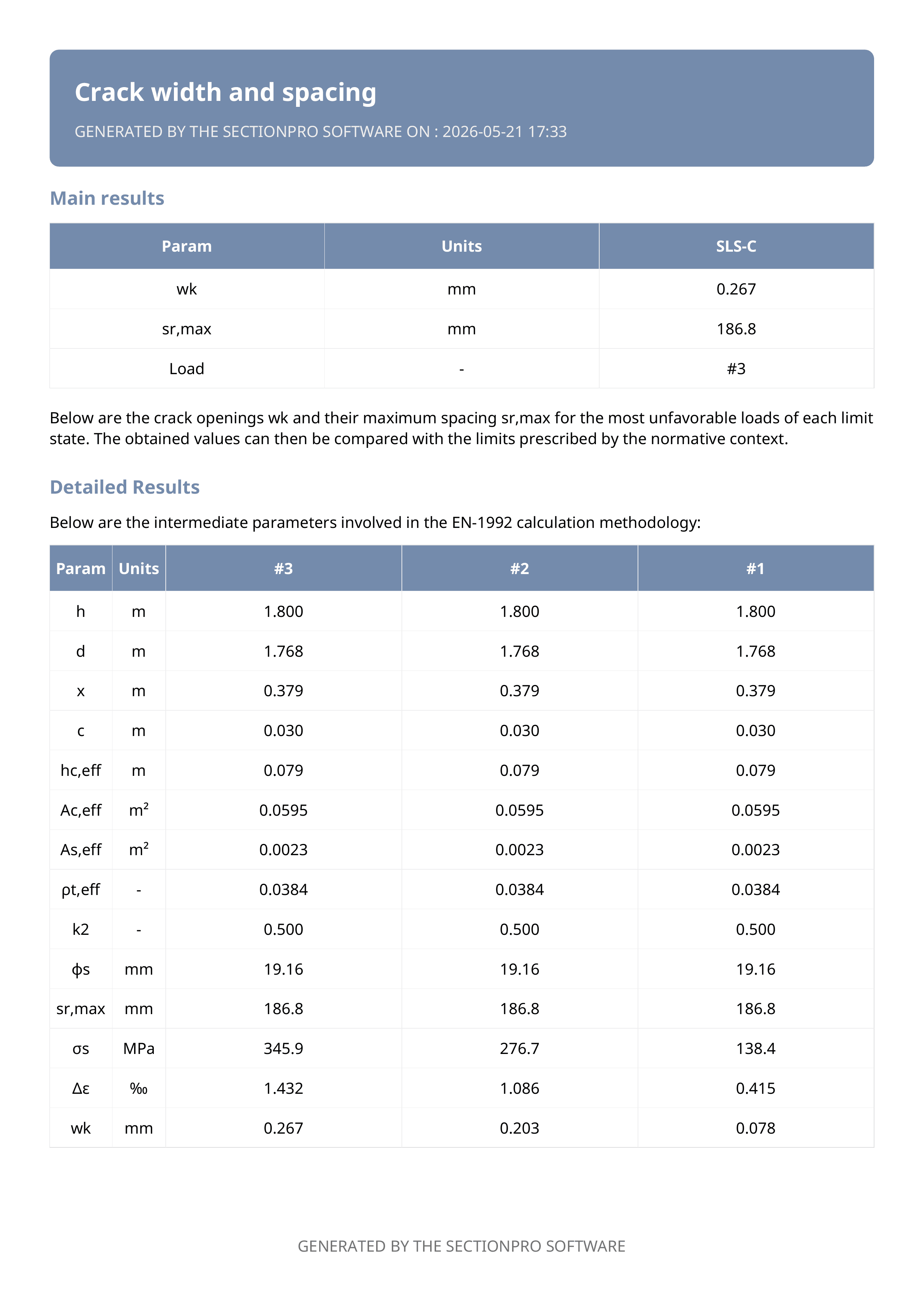
The crack width increases with the applied moment: mm at kN·m, mm at kN·m and mm at kN·m, all below the 0.3 mm limit. The crack spacing mm remains constant across all load levels since it depends only on geometry and reinforcement layout.
Benchmark
The crack width calculation is instantaneous: less than 10 ms for typical projects (up to 1,000 SLS load cases) and under half a second even for 100,000 cases.
Export
SectionPro exports the crack width analysis in three formats: PDF, text (fixed-width columns) and Excel (.xlsx). Exported data includes all results per load case (, , , , , etc.) sorted by decreasing .
Conclusion
The direct crack width calculation per EC2 §7.3.4 provides a rigorous assessment of the cracking state at the serviceability limit state. SectionPro automates the entire procedure: from the stress–strain analysis to the determination of the effective tension area , the crack spacing and the final crack width .
The two examples illustrate contrasting scenarios: a rectangular slab under bending and tension, and an I-beam under increasing bending moments.
The calculation applies to cross-sections of arbitrary shape: the effective tension area and reinforcement detection are computed from the general section geometry, without being limited to rectangular assumptions. The method is also applicable to other normative contexts by adapting the cracking parameters (, , , , ) to the values prescribed by the relevant design code.