

Introduction
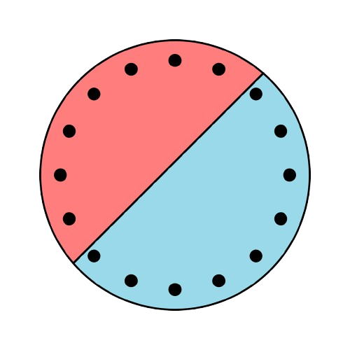
Real structures often combine several materials, voids, separate reinforcement layers, prestressing tendons or embedded steel members. Their analysis requires a representation that preserves both the geometry and the constitutive law of every component.
Defining an advanced section
An advanced section combines several families of mechanical objects. The kernel preserves their position in the section coordinate system and evaluates their contribution using the law assigned to each object.
- GeoDomains. An outer contour that may contain several voids; one section may contain several domains, each with its own material law.
- Passive reinforcement. Independent bar layers in which every bar has a position, diameter and steel law.
- Prestressing. Tendon families defined by their positions, areas, bond parameters and initial state.
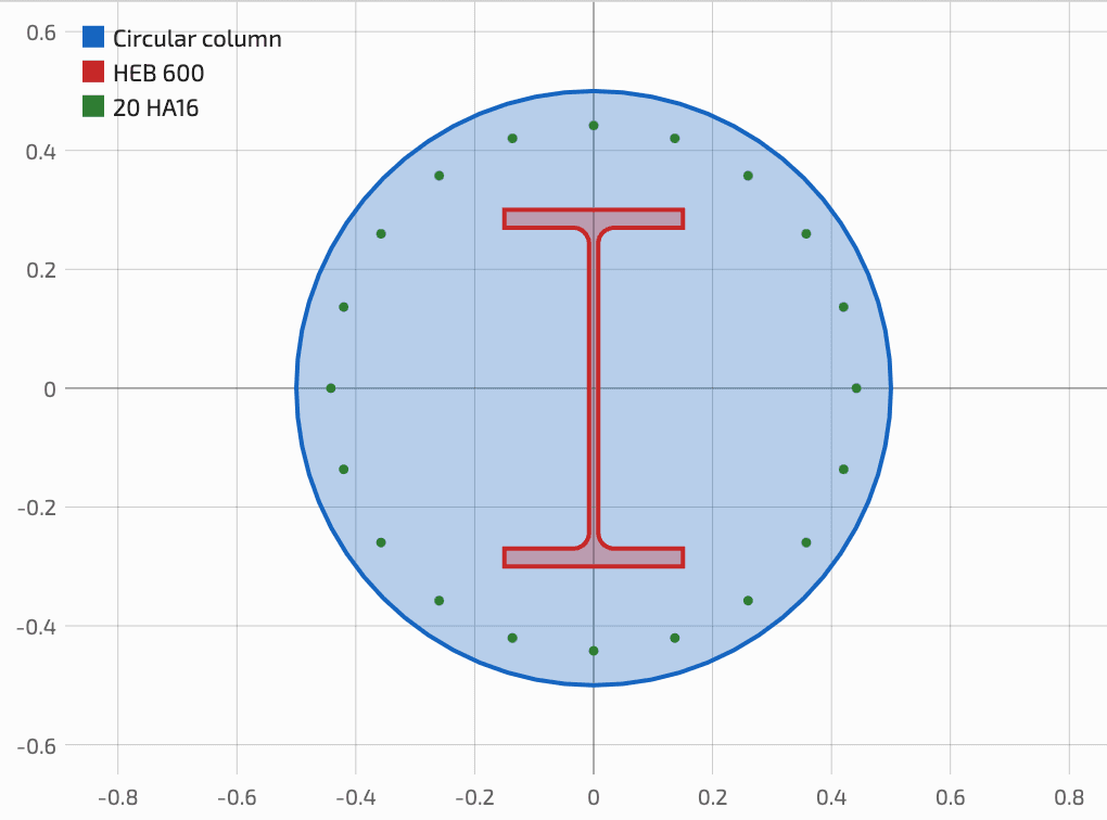
- Structural steel sections. An integrated library of 535 profiles covering eleven European families, represented by their actual area with curved transitions and fillets, or by TSP elements.
- TSP elements. The straight or curved midline and thickness of a plate, evaluated by line integration with stress assumed uniform through the thickness.
- Material laws. Built-in code models or a general user-defined stress–strain relationship.
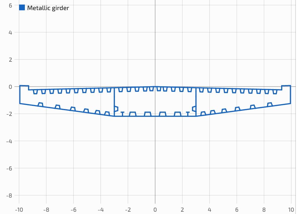
Example: bridge box girder
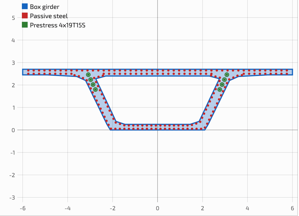
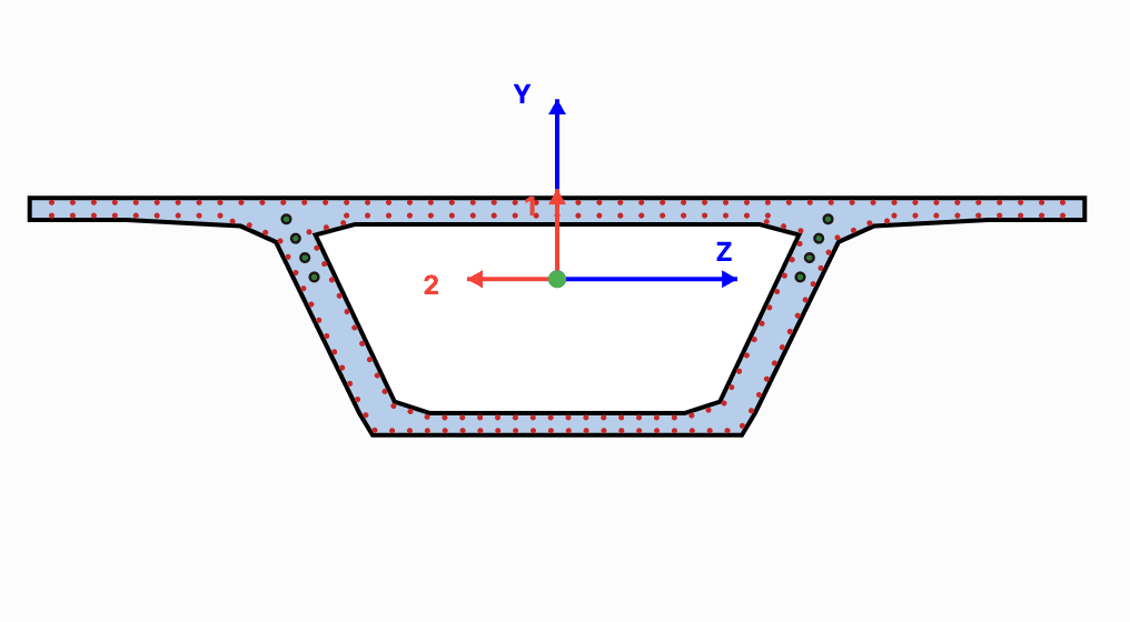
The example is a critical support section of a 12.00 m wide, 2.70 m deep single-cell box girder. Its C45/55 concrete domain contains one central void, 186 HA16 bars and eight 19T15S tendons arranged in groups of four along each web.
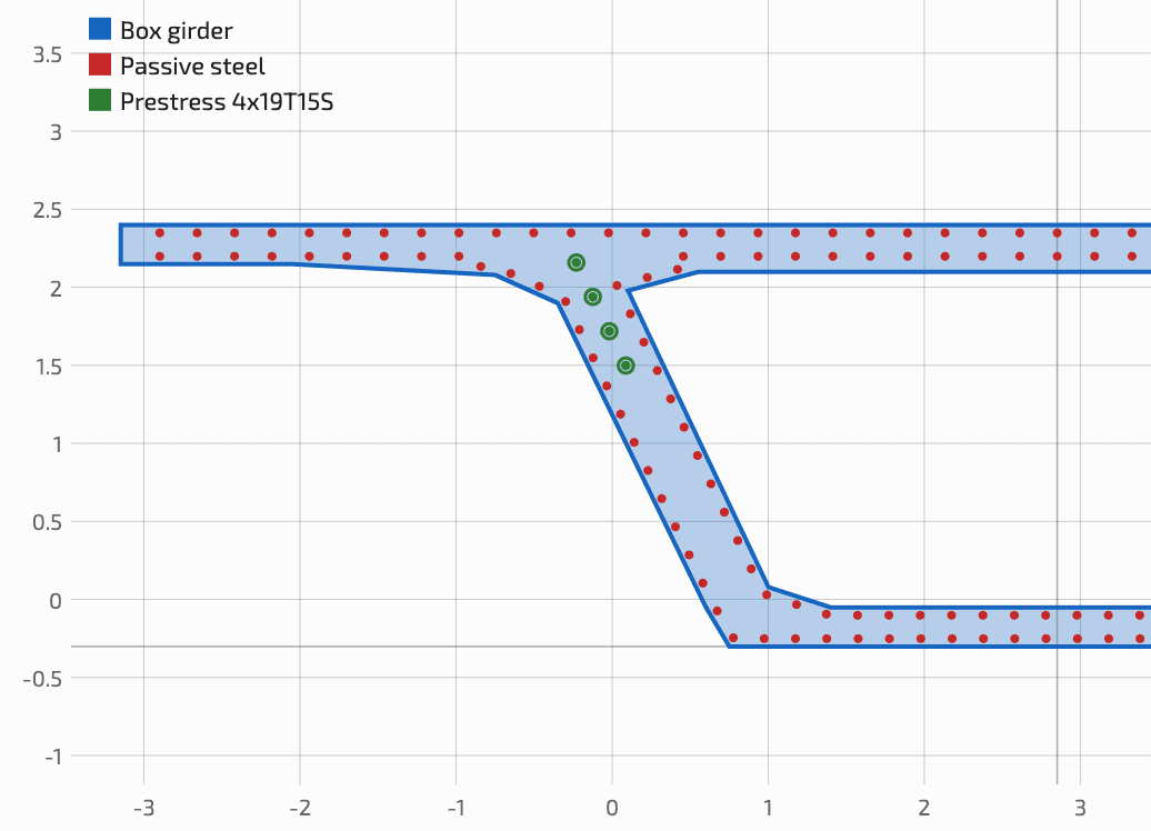
| Component | Material | Definition in the example |
|---|---|---|
| GeoDomain 1 | C45/55 | 12.00 × 2.70 m; A = 6.759 m² |
| Passive reinforcement | B500B | 186 HA16 |
| Prestressing | Y1860 | 8 × 19T15S; Ap = 2,850 mm²/tendon |
Section forces and prestressing
The total section-force vector is decomposed into permanent loads G, variable loads Q and prestressing P. The LFEM structural finite-element model supplies the G+Q effects; the prestressing action, including its primary and any secondary effect, must be included in the applied section-force vector.
The effective stress of 1116 MPa defines the initial tendon state. Their resistance contribution is then evaluated from the stress change induced by the equilibrium strain state, including any decompression of the adjacent concrete. Elongation produces a positive stress increment, while shortening decreases the tendon stress.
| Result | N [MN] | Mz [MN·m] | My [MN·m] |
|---|---|---|---|
| Characteristic SLS | 25.445 | −45.256 | 0.000 |
| Fundamental ULS | 25.445 | −79.256 | 0.000 |
Results on the full model
Mechanical characteristics
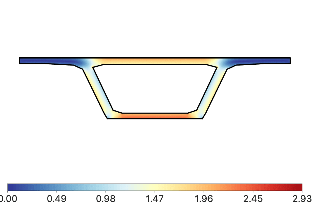
SectionPro calculates gross, net and transformed properties. In this example, only the prestressing ducts are deducted from the net section; passive reinforcement is retained. Torsion and shear properties are calculated on the same geometry.
| Section | A [m²] | yG [m] | Izz [m⁴] | Iyy [m⁴] |
|---|---|---|---|---|
| Gross | 6.7590 | 1.7765 | 6.4096 | 55.5258 |
| Net | 6.6962 | 1.7732 | 6.3979 | 54.9883 |
| Transformed | 6.9598 | 1.7777 | 6.5809 | 57.1632 |
Equilibrium at the SLS and ULS
The solver determines the section strain state that equilibrates the external section forces. Stresses follow from the respective constitutive laws of concrete, passive reinforcement and tendons. The results correspond to the characteristic SLS and fundamental ULS combinations.
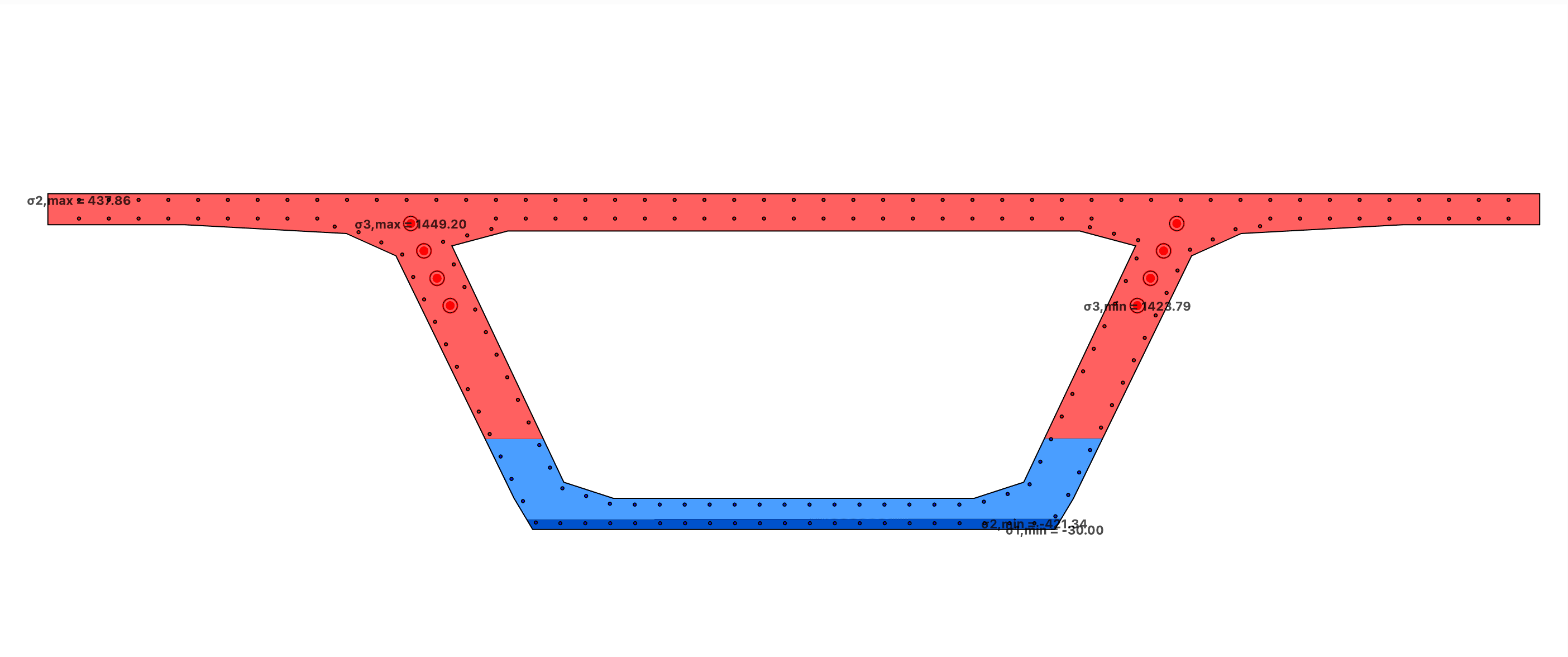
At the characteristic SLS, stresses remain well below the Eurocode 2 limits and the calculated crack width remains small at wk = 0.174 mm. At the ULS, the bottom-slab concrete locally reaches its plastic plateau and the tendons are strongly mobilized.
Interaction domains
The N–Mz curve is a slice through the domain at My = 0. The N–Mz–My surface extends the calculation to every bending direction. Its bounding box ranges from −26.70 to 231.62 MN in axial force, −100.41 to 105.35 MN·m about z, and −287.82 to 287.82 MN·m about y.
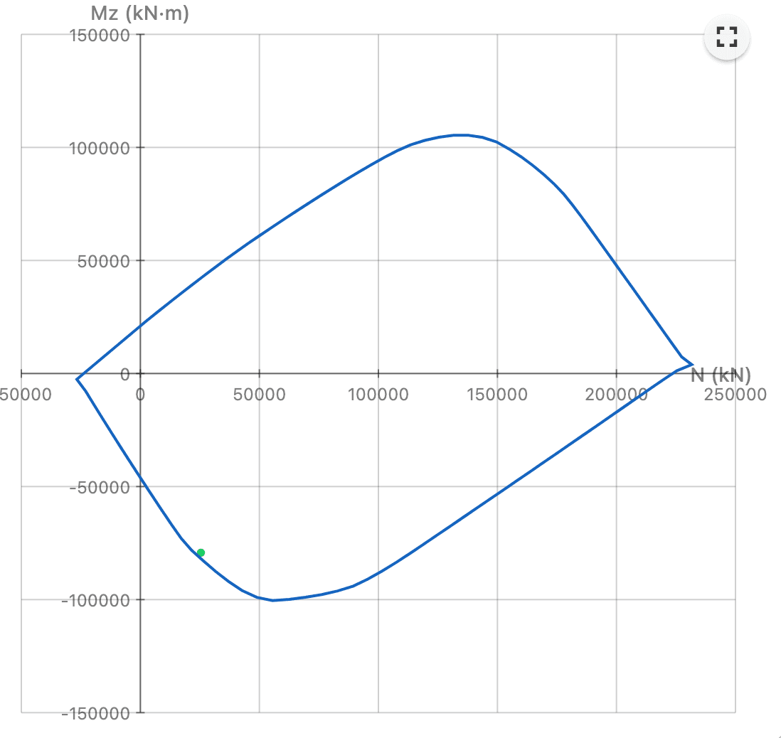
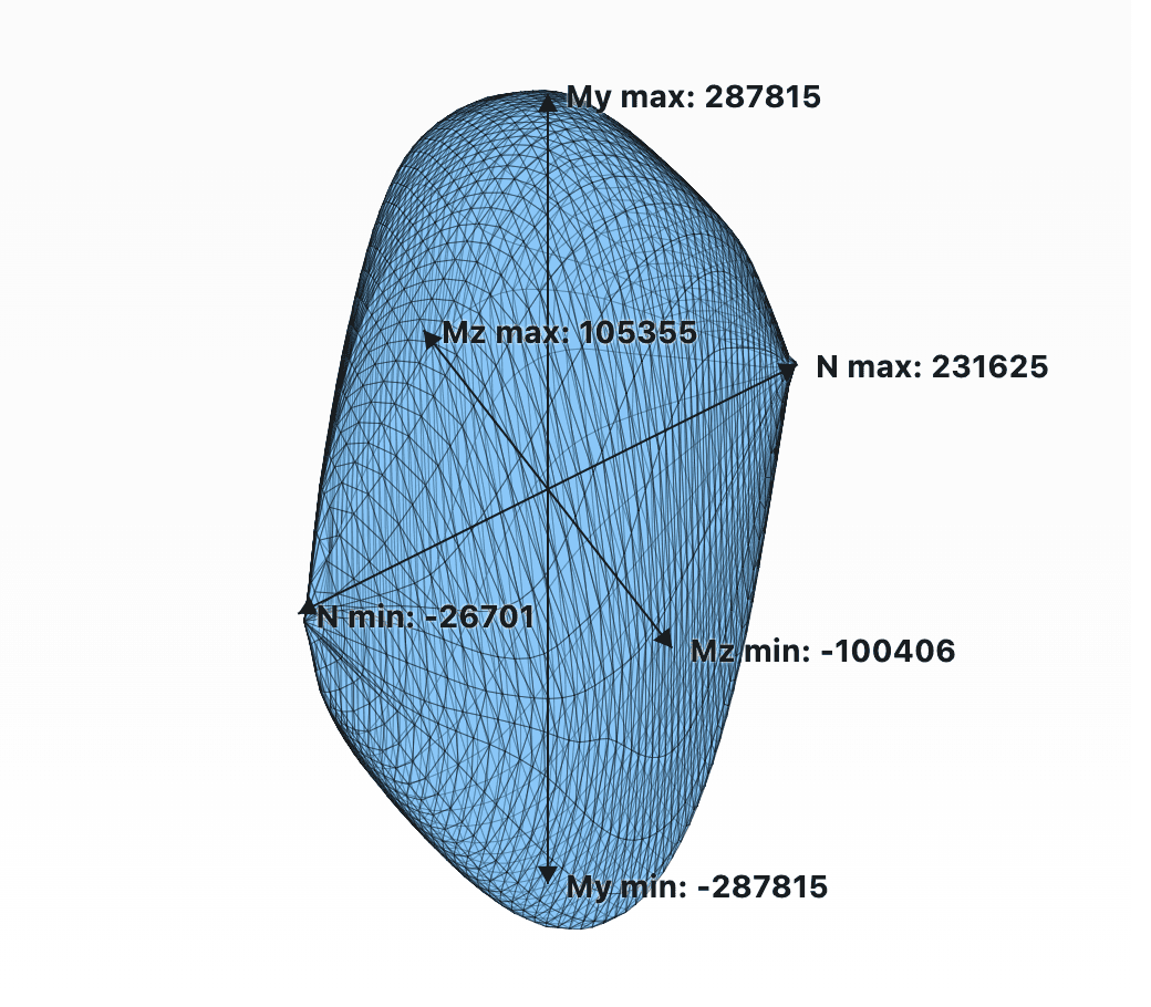
The final section-force vector lies immediately next to the resistance boundary. The distance-to-domain module gives FS = 0.983, slightly below unity but very close to the limit.
Performance
The timings below measure calls to the SectionPro kernel only, excluding the GUI and rendering. Kernel optimization keeps calculations nearly instantaneous, including nonlinear equilibrium and construction of the three-dimensional resistance domain.
| Analysis | Kernel time |
|---|---|
| Mechanical characteristics | 28.3 ms |
| Equilibrium at the SLS and ULS | 0.73 ms |
| Crack-opening calculation | 2.38 ms |
| N–Mz (200 points) | 1.11 ms |
| N–Mz–My (50 × 50) | 208 ms |
Conclusion
Advanced mode can handle virtually any cross-section, regardless of geometry or constituent materials, under the usual assumptions of cross-section analysis: plane sections remain plane and linked components satisfy strain compatibility. This generality retains near-instantaneous response times.